A320 Simulation — Overview
Our A320 software solution simulates the full airbus avionics and aircraft systems and is aimed at professional flight simulator manufacturers that are looking for a solution to integrate it into their simulator hardware.

The history behind
A passionate hobby project that grew into a full-fledged solution.
Starting out small, one module at a time, the development of the first generation of our A320 simulation software took multiple years and was intended as a hobby project for personal use. You can read all about it at www.a320simulator.be.
Over time many modules were added, the solution architecture was improved, we introduced the usage of real Arinc 424 NavDb, introduced open interfacing towards hardware and completely rebuild the graphical user interfaces.
Features
Our A320 simulation solution has a unique architecture that offers flexibility, scalability and extensibility.
Modular Design
The different cockpit components are developed as separate stand-alone applications. These cockpit modules can be launched independently. An application manager is provided that allows you to launch any application anywhere in the network.
Distributed Architecture
The different cockpit modules can be distributed over multiple PC’s connected over a network and automatically discover each other. Running all modules on a single high performant PC is also possible.
Multi Platform
The cockpit modules can run either on Microsoft Windows PC or on Raspberry Pi. This way the most space efficient and cost effective implementation is possible. Raspberry Pi deployment makes our software ideal for building stand-alone integrated instruments.
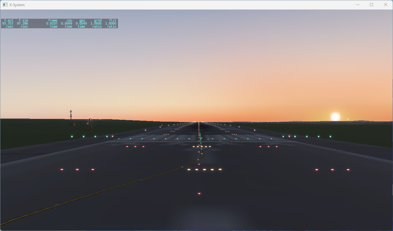
Simulator Package Agnostic
Like the real aircraft, our software gathers all data through the real aircraft sensors, internally processes it and sends back the position of the aircraft control surfaces to the flight sim package (X-Plane, Microsoft Flight Simulator, Lockheed Martin Prepar3D). This makes our solution simulator package agnostic.
Efficient Hardware Interfacing
We use CAN (Controller Area Network) based communication to interface with cockpit hardware components. An ICD (Interface Control Document) specifies all messages and their format. Off-the-shelf CAN-to-LAN Gateways can be used to communicate with hardware.
Touchscreen Virtual Hardware
For all real hardware panels that exists in the cockpit, a virtual software simulated equivalent is provided that is fully touchscreen compatible. You can mix and match real and virtual simulated hardware. Enabling you to go from a full software touchscreen procedure trainer upto a full hardware flight training device.
Specification
In our A320 simulation solution we aim to reproduce with high fidelity well specified aircraft models, engine types and systems.

- Aircraft family: A320-200 (CEO)
- Aircraft models: A320-214 or A320-232
- Engine versions: CFM56-5B4 or IAE V2527-A5
- Navigation Database: native ARINC 424
- EIS: EIS1 or EIS2 standard
- FMGC: FMS Thales R1A
- EGPWS: Honeywell MK V and MK VII
- TCAS: Honeywell CAS-81A (TCAS II Change 7.0)
- WXR: Honeywell RDR-4B
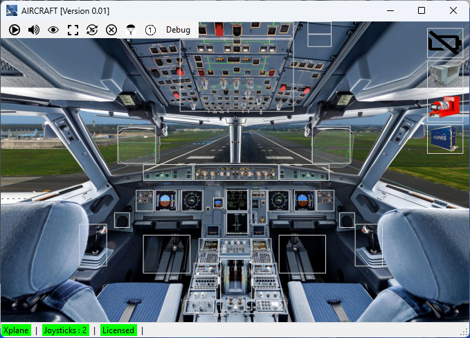
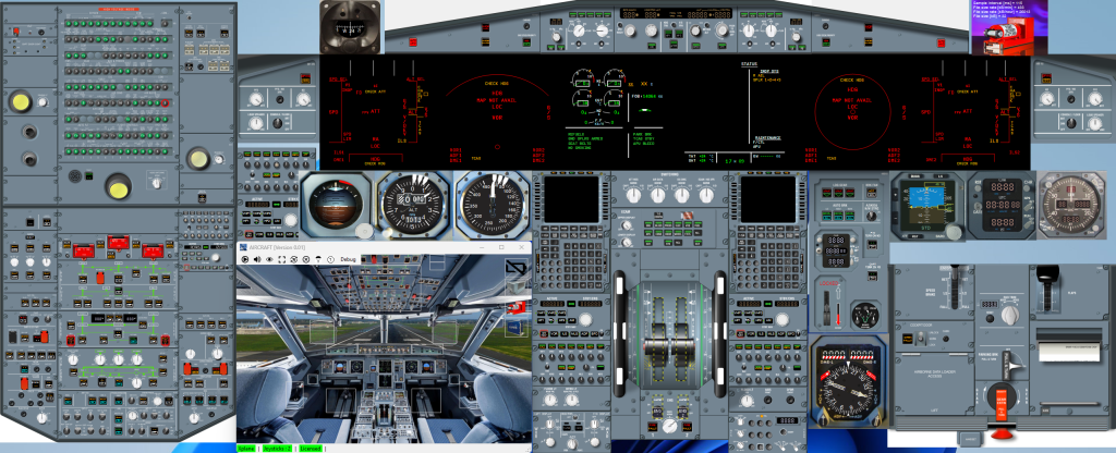
Main Application
The main application allows to control all the application modules in the A320 Simulator solution. By clicking on the white squares of a specific item in the main application, that particular application is minimized or shown on screen again. In a desktop trainer configuration this is handy to declutter the desktop of unused modules.
Application Modules
Electronic Instrument System (EIS)
Four Display Units (DU’s) provide pilot side and co-pilot side Primary Flight Display (PFD) and Navigation Display (ND).
Two additional DU’s provide ECAM Engine/Warning Display and ECAM System Display.
Both EIS1 and EIS2 standards are simulated.
EIS1


EIS2


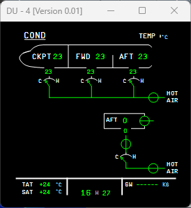
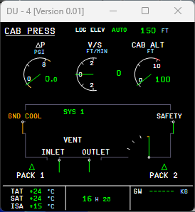
Electronic Centralized Aircraft Monitor (ECAM) – System Display (SD)
All 12 system pages are provided, with elaborated simulation of the aircraft systems they visualize.
Both EIS1 and EIS2 standards are simulated.
EIS1


EIS2


Flight Controls and Autoflight
Flight Controls are simulated fully by 2 ELACs (Elevator Aileron Computer), 3 SECs (Spoilers Elevator Computer) and 2 FACs (Flight Augmentation Computer).
Autoflight is simulated in a full dual FMGC (Flight Management Guidance Computer) – MCDU (Multipurpose Control and Display Unit) configuration, combined with a stand-alone FCU (Flight Control Unit)


Pilot Controls
We implemented flexible assignment of the pilot controls (Throttle Levers, Engine Switches, Trim Wheel, Flaps, Speed Brakes, Parking Brake, Gear Lever,…) to either be used from the virtual hardware panels or from real hardware (e.g. joystick and throttle).
By a simple right mouse click on the specific item the control is toggled between real and virtual hardware. A yellow-black dashed outline indicates that control is assigned to real hardware.


Overhead
We simulate both the lower overhead panel as well as the upper overhead panel.
All the aircraft systems that the lower overhead panels controls are extensively simulated:
- EXT LT (External Lights)
- APU
- AIR COND (Air Conditioning)
- ELEC (Electrical)
- FUEL (Fuel)
- HYD (Hydraulic)
- FIRE (Fire)
- ADIRU (Air Data Inertial Reference Unit)
- FLT CTL (Flight Control)
- GPWS (Ground Proximity Warning Syste,)
In the electrical system, more that 170 Circuit Breakers (C/B’s) are simulated. Like in the real aircraft, the most important C/B’s that the pilots need to be able to access immediately are in our simulation also available in the simulated upper overhead panel.


Traffic Collision Avoidance System (TCAS)
Our generic TCAS simulation solution that is build for all of our simulation products can also be used in the A320 simulation solution. The TCAS data is integrated into the PFD and ND, and the TCAS Control Panel can be used to control it.

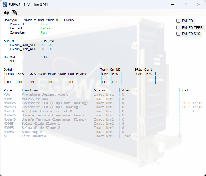
Enhanced Ground Proximity Warning System (EGPWS)
Our generic EGPWS simulation solution that is build for all of our simulation products can also be used in the A320 simulation solution. Terrain data is integrated into the ND and all EGPWS Modes are available with callouts (PDA, Mode1, Mode2A/B, Mode3, Mode4A/B, Mode, Mode 6) as well as altitude callouts.


Flight Warning Computer (FWC)
We fully emulate the real FWC logic, including the Arinc 429 communication with the System Data Acquisition Concentrators (SDAC).
At present 474 Primary, Secondary and Independent Failures and 258 Inoperative Systems have been implemented. That represents overall approximate 61% completion.
Check out the tabs that give an overview of what has been implemented per ATA Chapter.
Digital Flight Data Recorder (DFDR)
Our DFDR records all of the key flight parameters and stores them to file for post processing. We developed an extensive flight analysis tool to view and visualize the full flight data which we store in a data lake.


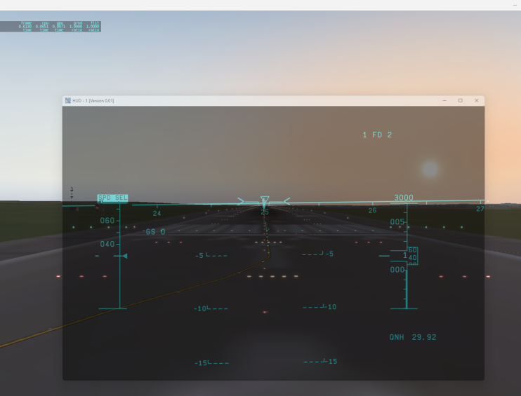
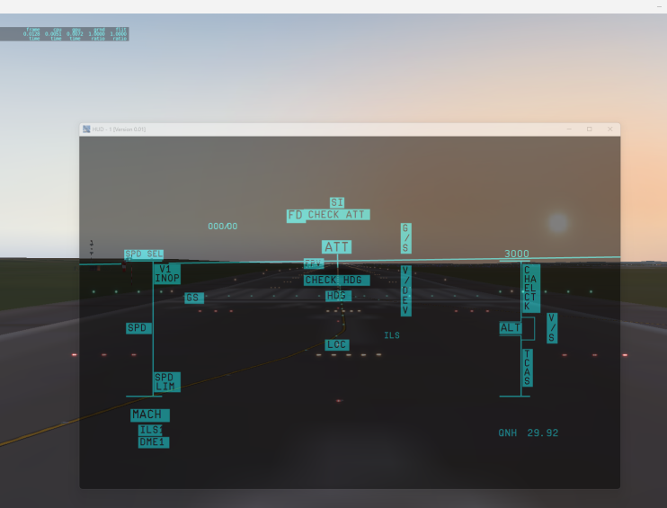
Head-Up Display
We simulate dual (pilot and co-pilot) Head-Up Displays.
The transparency can be set according to the light conditions.
The HUD features advanced functionaly such as Synthetic Runway Visualization.


Standby Instruments
We simulate both the 4 separate classic standby instruments (Horizon, Airspeed Indicator, Altitude Indicator, Magnetic Compass), as well as the modern electronic Integrated Standby Instrument System (ISIS).
Classic Standby Instruments


Integrated Standby Instrument System

Clock
We simulate both the classic analog clock used in the older A320’s, as well as the new digital clock used on recent aircraft.
Analog Clock

Digital Clock

Digital Distance Radio Magnetic Indicator (DDRMI)
Only used in older A320’s, but we also simulate the DDRMI which displays magnetic heading VOR1 and VOR2, magnetic bearings, ADF1 and ADF2, and DME1 and DME2 distances.

Annunciator Light Test
With the annunciator light switch on the overhead the sim can be set to the annunciator light test mode. Click on the image below to see it in full view.
Ready For Take-Off
We are happy to learn about your A320 plans and see how we can support you.